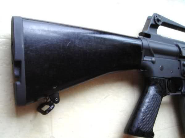
Following My65PAN’s instructions, here’s how a friend and I installed a MY65PAN 607 stock onto an NDS XM
Lower. Sorry for the crappy pics but I was juggling several things at once.
607 “Pin-On” Stock Installation
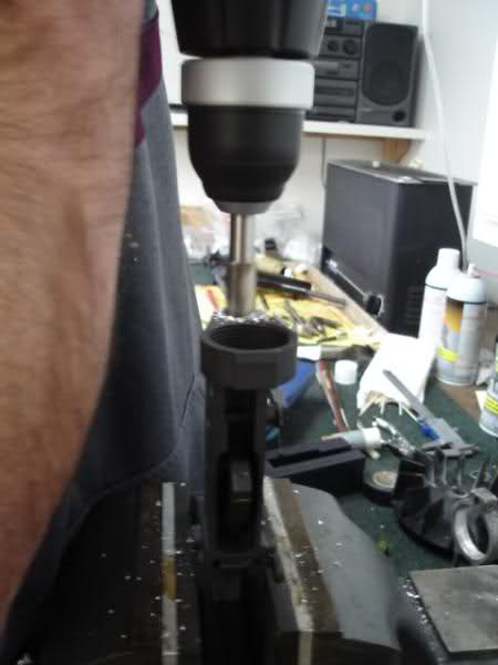
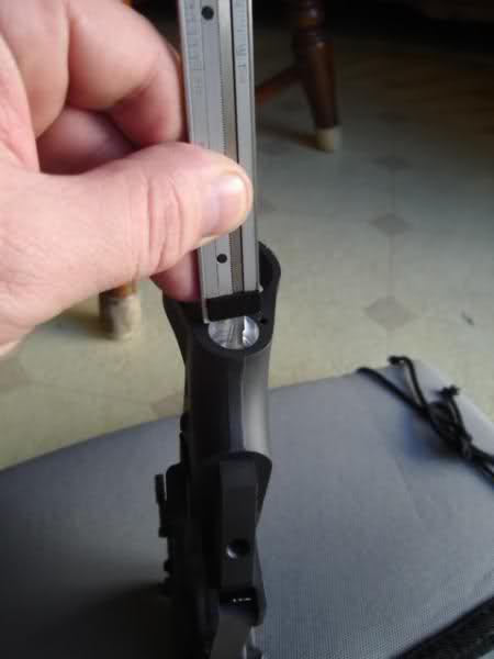
1. Drilling out the lower receiver hole.
First the lower receiver was squared up using a small level and clamped in a padded vice. Next using a ½
inch end mill bit, the lower receiver hole was drilled to a total depth of .365. It just started to get into the
buffer retainer hole. We used a standard 19v Hand drill at medium speed, checking depth with the calipers
every so often. The goal here is to drill out the lower rod hole as close to the buffer retaining hole as possible
without going into it. The depth of your receiver hole may be different than mine.
**NOTE** The buffer retaining hole slopes at a 6 degree angle downward toward the rear of the receiver.
Also the recently posted authentic Colt 607 pics show the lower locking rod traversing completely through the
buffer retaining hole….but that’s another story.
One person drilled while the other checked for straightness. You should have a good drill, a quality sharp bit,
and a steady hand to avoid any wobble. The hole came out very nice. We went the hand route, but a drill
press would make for a more accurate install.
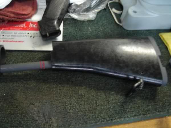
2. Measuring the locking rod.
From the end face of the receiver to the bottom of the drilled lower rod hole, calculate the depth. I used the
“Depth Probe” part of the caliper to calculate the depth. In my case the hole depth was .365. Yours may be
different so always measure 14 times.
With the stock in the locked closed position, we measured .365 (The depth of our hole) from the lower lock
rod lip and scribed a mark on the rod. We then added 1/16” and scribed a second mark. This extra 1/16” scribe
mark is where we will make the first cut. The extra material is added, just to be safe.
[span style='font-weight: bold;']3. Cutting the rod to length.[/span]
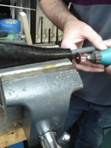
3. Cutting the rod to length.
The rod was then cut using a Dremel and cut-off wheel. Kinda slow, but made for a nice cut. We then re-fit
the rod to the receiver and measured again.
Confident with our measurement, the last(extra) 1/16” was ground off and squared up on a grinding wheel,
measuring for fit as we went along.
The cutting and grinding were accomplished with the stock assembled. Be sure to work slow and cool the rod
with water periodically to avoid excessive heat buildup.
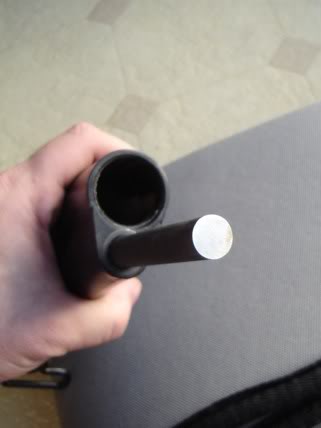
4. Shaving the buffer tube lip.
Because the buffer tube lip can interfere with locking tube lip when the assembly is closed, a little material
must be removed from one or the other. I just couldn’t bring myself to mess with such a beautiful stock so I
opted to take a little off the bottom edge of the buffer tube lip with the Dremel.
Screw the tube tight onto your lower receiver and mark the area you want to remove. The tube is an RRA Entry
tube, easily replaced if need be. Remove the material.
That's a tough place to get a good photo of when assembled. Sorry I didn't get an "in progress" pic.
I tightened the tube to the lower receiver and with a Sharpie marked about a 3/8" area where the lower lock
rod hits the buffer tube lip.
The buffer tube was placed in a vice. The lip is round and I ground a small 3/8" flat area on the bottom of the
buffer tube lip. Very little material was removed to work, maybe 1/32nd. I used a dremel with a round high
speed cutter bit, then a file.
Now you should tighten your tube a few times to get the true bottom of where the locking rod will hit. On my
final assembly I was able to tighten the tube a hair more, but still had clearance.
MS Paint
Area in red is material removed.
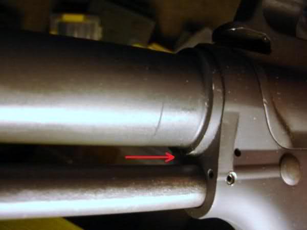
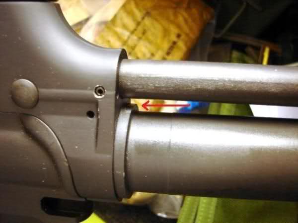
I had my buffer tube anodized XM Gray before the mod, so the area is shiny in that spot. I recommend modding
the buffer tube before anodizing, though you cannot see the area when assembled.
The pics are vague, but that's best I can do right now under flourescent lights. Arrows show area where
material was removed.
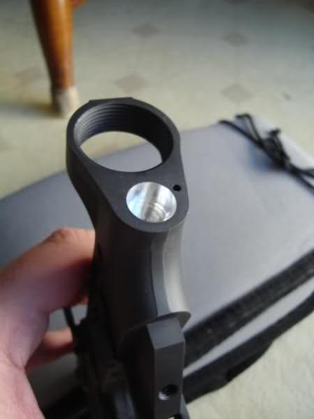
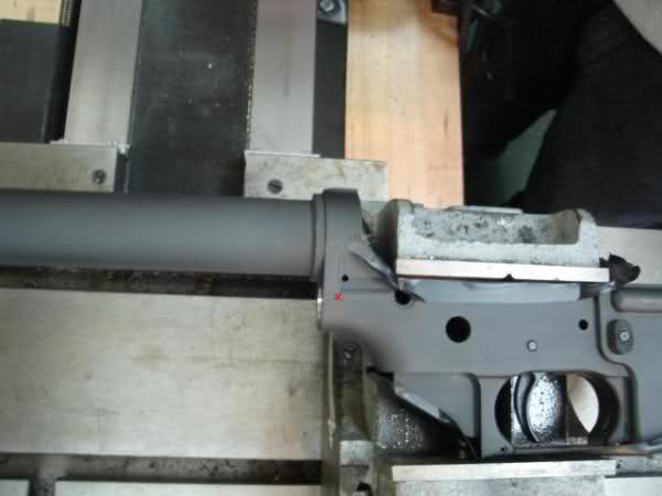
5. Marking the cross-pin hole.
You’ll see that the cross-pin needs to intersect the lower locking rod and traverse across the receiver from
left to right. We eyeballed our mark from looking at many 607 photos . The cross-pin needs to capture the rear
takedown pin detent spring. Roughly 1/8” - 3/16" in from the receiver end face and just below center of the
rear takedown pin detent spring hole. X marks the spot. Scribe it.
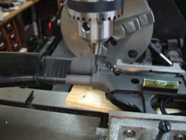
6. Drilling and seating the cross-pin hole.
Now is not the time for that Guinness, or maybe it is.
The lower receiver was clamped and leveled into our milling machine and the bit chucked up. My roll pin was
a standard Ace Hardware tension pin 1/8 by 7/8, just like My65PAN says to use. My pin measured .129 in
diameter.
The bit wanted to wander a little bit at first until it got a good bite on the metal. Use a pointed center punch to
tap a starter indentation. You really need a good quality sharp bit. We opted to use a smaller bit than the pin at
.125. Your pin size may vary. Drill it, left side only.
Insert the buffer tube and buffer retaining spring and plunger. Next LOCK the stock in the OPEN position and
install the stock assembly onto the buffer tube, and insert the lower locking rod into the lower receiver hole,
bottoming it out. Then wrap electrical tape nice and tight around the buffer tube and lower rod to hold them in
that position. Make sure the lever lock is in the “L” position.
Make sure everything is clamped up tight. Align your bit through your existing hole and drill the rod straight
on through to the other side of the receiver. Make sure your stock assembly is held straight and tight in the
hole while drilling.
Once drilled, our roll pin was polished up and checked for burrs. Start the pin by tapping it in with a Roll Pin
Holder Punch. Just get it started and stop. A little CLP helps.
To install the rear takedown pin detent spring, you will need to cut off a few coils from the spring. Insert the
detent, rear takedown pin, and then the spring, then use a small punch to hold the spring in place, far enough
to clear the cross-pin. Then drive the pin home.
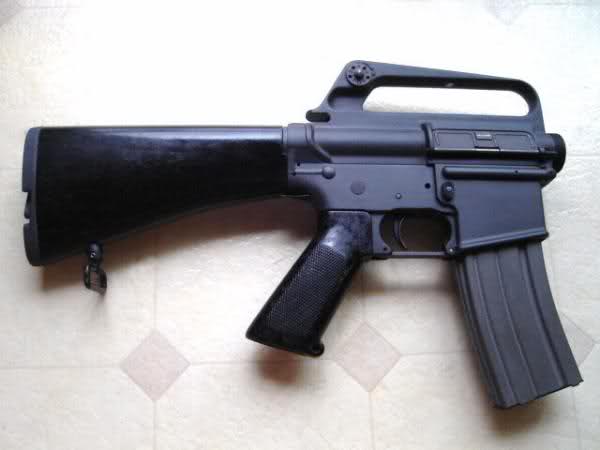
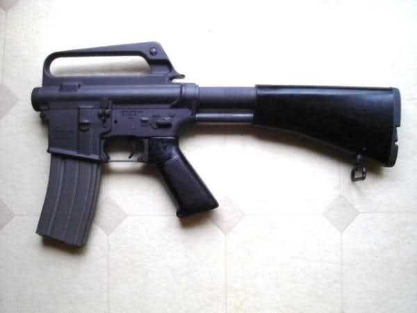
I can’t begin to describe how awesome this stock is now that’s installed. It’s tight, solid and locks up
perfectly. It feels very secure and Mark’s precision machining is spot on.. The stock is truly a functional work
of art. I hope this helps somebody who is hedging that 607 build for fear of boogering it up like I was. Thanks
Mark, Tom A. and everyone else for the info. Now did I just hear someone say 608?[/span]
Thank You Mark for offering such a great stock !
At the last minute I opted to go with an original 604 upper and the NDS XM16E1 lower instead of the NDS A1
lower.
I highly recommend the stock to everyone. The install is really easier than it looks and a lot of fun.
Hal
Lower. Sorry for the crappy pics but I was juggling several things at once.
607 “Pin-On” Stock Installation
1. Drilling out the lower receiver hole.
First the lower receiver was squared up using a small level and clamped in a padded vice. Next using a ½
inch end mill bit, the lower receiver hole was drilled to a total depth of .365. It just started to get into the
buffer retainer hole. We used a standard 19v Hand drill at medium speed, checking depth with the calipers
every so often. The goal here is to drill out the lower rod hole as close to the buffer retaining hole as possible
without going into it. The depth of your receiver hole may be different than mine.
**NOTE** The buffer retaining hole slopes at a 6 degree angle downward toward the rear of the receiver.
Also the recently posted authentic Colt 607 pics show the lower locking rod traversing completely through the
buffer retaining hole….but that’s another story.
One person drilled while the other checked for straightness. You should have a good drill, a quality sharp bit,
and a steady hand to avoid any wobble. The hole came out very nice. We went the hand route, but a drill
press would make for a more accurate install.
2. Measuring the locking rod.
From the end face of the receiver to the bottom of the drilled lower rod hole, calculate the depth. I used the
“Depth Probe” part of the caliper to calculate the depth. In my case the hole depth was .365. Yours may be
different so always measure 14 times.
With the stock in the locked closed position, we measured .365 (The depth of our hole) from the lower lock
rod lip and scribed a mark on the rod. We then added 1/16” and scribed a second mark. This extra 1/16” scribe
mark is where we will make the first cut. The extra material is added, just to be safe.
[span style='font-weight: bold;']3. Cutting the rod to length.[/span]
3. Cutting the rod to length.
The rod was then cut using a Dremel and cut-off wheel. Kinda slow, but made for a nice cut. We then re-fit
the rod to the receiver and measured again.
Confident with our measurement, the last(extra) 1/16” was ground off and squared up on a grinding wheel,
measuring for fit as we went along.
The cutting and grinding were accomplished with the stock assembled. Be sure to work slow and cool the rod
with water periodically to avoid excessive heat buildup.
4. Shaving the buffer tube lip.
Because the buffer tube lip can interfere with locking tube lip when the assembly is closed, a little material
must be removed from one or the other. I just couldn’t bring myself to mess with such a beautiful stock so I
opted to take a little off the bottom edge of the buffer tube lip with the Dremel.
Screw the tube tight onto your lower receiver and mark the area you want to remove. The tube is an RRA Entry
tube, easily replaced if need be. Remove the material.
That's a tough place to get a good photo of when assembled. Sorry I didn't get an "in progress" pic.
I tightened the tube to the lower receiver and with a Sharpie marked about a 3/8" area where the lower lock
rod hits the buffer tube lip.
The buffer tube was placed in a vice. The lip is round and I ground a small 3/8" flat area on the bottom of the
buffer tube lip. Very little material was removed to work, maybe 1/32nd. I used a dremel with a round high
speed cutter bit, then a file.
Now you should tighten your tube a few times to get the true bottom of where the locking rod will hit. On my
final assembly I was able to tighten the tube a hair more, but still had clearance.
MS Paint
Area in red is material removed.
I had my buffer tube anodized XM Gray before the mod, so the area is shiny in that spot. I recommend modding
the buffer tube before anodizing, though you cannot see the area when assembled.
The pics are vague, but that's best I can do right now under flourescent lights. Arrows show area where
material was removed.
5. Marking the cross-pin hole.
You’ll see that the cross-pin needs to intersect the lower locking rod and traverse across the receiver from
left to right. We eyeballed our mark from looking at many 607 photos . The cross-pin needs to capture the rear
takedown pin detent spring. Roughly 1/8” - 3/16" in from the receiver end face and just below center of the
rear takedown pin detent spring hole. X marks the spot. Scribe it.
6. Drilling and seating the cross-pin hole.
Now is not the time for that Guinness, or maybe it is.
The lower receiver was clamped and leveled into our milling machine and the bit chucked up. My roll pin was
a standard Ace Hardware tension pin 1/8 by 7/8, just like My65PAN says to use. My pin measured .129 in
diameter.
The bit wanted to wander a little bit at first until it got a good bite on the metal. Use a pointed center punch to
tap a starter indentation. You really need a good quality sharp bit. We opted to use a smaller bit than the pin at
.125. Your pin size may vary. Drill it, left side only.
Insert the buffer tube and buffer retaining spring and plunger. Next LOCK the stock in the OPEN position and
install the stock assembly onto the buffer tube, and insert the lower locking rod into the lower receiver hole,
bottoming it out. Then wrap electrical tape nice and tight around the buffer tube and lower rod to hold them in
that position. Make sure the lever lock is in the “L” position.
Make sure everything is clamped up tight. Align your bit through your existing hole and drill the rod straight
on through to the other side of the receiver. Make sure your stock assembly is held straight and tight in the
hole while drilling.
Once drilled, our roll pin was polished up and checked for burrs. Start the pin by tapping it in with a Roll Pin
Holder Punch. Just get it started and stop. A little CLP helps.
To install the rear takedown pin detent spring, you will need to cut off a few coils from the spring. Insert the
detent, rear takedown pin, and then the spring, then use a small punch to hold the spring in place, far enough
to clear the cross-pin. Then drive the pin home.
I can’t begin to describe how awesome this stock is now that’s installed. It’s tight, solid and locks up
perfectly. It feels very secure and Mark’s precision machining is spot on.. The stock is truly a functional work
of art. I hope this helps somebody who is hedging that 607 build for fear of boogering it up like I was. Thanks
Mark, Tom A. and everyone else for the info. Now did I just hear someone say 608?[/span]
Thank You Mark for offering such a great stock !
At the last minute I opted to go with an original 604 upper and the NDS XM16E1 lower instead of the NDS A1
lower.
I highly recommend the stock to everyone. The install is really easier than it looks and a lot of fun.
Hal
RETRO BLACK RIFLE - HOW TO INSTALL 607 STOCK
| | | | | |
How To Install A 607 Stock
Written by Hal143
Written by Hal143

| "RETRO" BUILD GUIDE |
| .223 Cal / 5.56mm |